Guide to Pipe Wall Thickness and Inside Diameter Calculation
Step-by-step guide to determining the correct pipe size based on fluid dynamics principles.
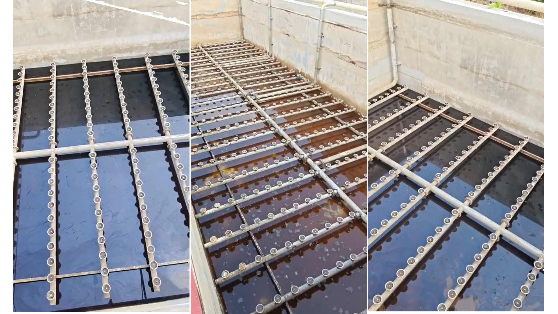
For calculating pipe sizing we need two separate engineering decisions but before we talk about that, make sure the P&ID drawing is comply the iso standard. First we talk about the *inside diameter is decided based on how fast the fluid moves and how much pressure it loses on the way. Second we talk about the wall thickness based on condition whether the pipe survives that pressure — plus whatever the ground, the traffic overhead, or the pipe rack throws at it — without failing. If you failed in both calculation you will pay for it every day, in pump energy, noise, or erosion.
Before we talk about thickness and diameter we need to start from: velocity, sanity-check the economics, and then size the wall for pressure and any external load.

1. Start from velocity, not e start from diameter
The fastest route to a workable pipe size is to pick a sensible fluid velocity for the service, then solve for diameter using continuity:
Choosing the right fluid velocity is a very important part of piping design. It has strict maximum and minimum limits. If you want the velocity is slow, and you choose too larger pipes, it was lead on wastes money on extra materials and insulation. On the other hand, if you want the velocity is fast, and you choose too small pipes, it causes many operational problems. These include loud noise, vibration, pipe wall erosion, and severe water hammer when the fluid stops suddenly. Also, high velocity at the pump suction can drop the pressure below the vapor pressure, which causes a problem called cavitation. These problems get worse if the velocity distribution is not even. This usually happens because of a bad piping layout. Therefore, designing a good pipe layout is just as important as calculating the velocity itself.
Typical starting ranges, by service:
| Service | Typical velocity | Why |
|---|---|---|
| General liquid, pump discharge | 1–3 m/s (3–10 ft/s) | Balances pipe cost against friction loss |
| Pump suction lines | Lower than discharge | Preserves available NPSH, avoids cavitation |
| Water piping — brass | 1.2–4.6 m/s (4–15 ft/s) | Material is fairly erosion-tolerant |
| Water piping — carbon steel | 2.1–3 m/s (7–10 ft/s) typical | Higher velocities need erosion-resistant material |
| Water piping — erosion-resistant alloys (e.g. stainless) | Up to ~9 m/s (30 ft/s) | Material tolerates the higher shear |
| Cryogenic liquids | ~1.5 m/s (5 ft/s) | Limits flashing and two-phase effects |
| Gas lines, general | 15–65 m/s (50–200 ft/s) practical range, up to ~130 m/s (400 ft/s) ceiling | Gas is far less erosive than liquid, but pressure drop and noise still climb fast |
These are starting points, not code requirements — always check the governing project spec or code for the service in question.
Why velocity is the right first variable, not an afterthought: pressure loss to friction scales with velocity squared (the Darcy-Weisbach relationship, ). Push velocity up 20% and friction loss goes up roughly 44%. That nonlinearity is the entire reason a "slightly smaller, slightly faster" pipe can quietly turn into a pumping-cost problem — and it's also what the economic check in the next step is actually optimizing against.
2. Refine with an economic diameter check
Velocity gives you a good, fast starting diameter. For long runs or anything with a real pumping/compression power bill attached — gas transmission lines, long transfer lines, compressor discharge piping — it's worth checking whether that starting diameter is actually the cheapest one over the system's life. Smaller pipe costs less to install but more to operate (higher friction loss, more compressor or pump power); larger pipe flips that trade. Somewhere between the two is a minimum-total-cost diameter.
For compressible/gas service, a widely used correlation for that economic diameter takes this form:
| Symbol | Meaning |
|---|---|
| Inside pipe diameter (in) | |
| Molecular weight of the gas | |
| Absolute temperature | |
| Average compression temperature | |
| Cost of power ($/kW·h) | |
A metric-unit version of the same relationship exists with an adjusted leading constant. In practice, most day-to-day plant piping never runs this calculation — the velocity method above, combined with a pressure-drop check, is close enough. This formula earns its keep specifically when power cost dominates the lifecycle cost, which is a compressor or transmission-line problem more than a plant-piping one.
One practical habit worth carrying over regardless of which method you use: size in some headroom. Lines almost always pick up extra fittings, control valves, and the occasional future tie-in after commissioning, and a line sized to the bare theoretical minimum has no room left to absorb any of it.
3. Size the wall for pressure
Once the diameter is set, wall thickness is a pressure problem. For a thin-walled cylinder, the governing stress is hoop (circumferential) stress, and the classic relationship — Barlow's formula — is:
where is allowable stress, is internal pressure, is diameter, and is wall thickness. It's a good way to build intuition, but piping codes (ASME B31.1 for power piping, B31.3 for process piping) use a more complete version that accounts for how the pipe is actually made and what will happen to it in service:
| Symbol | Meaning |
|---|---|
| Minimum required wall thickness | |
| Internal design pressure | |
| Outside diameter | |
Two of these terms are easy to underrate:
- Joint efficiency () separates seamless pipe () from the various welded constructions, which are rated lower depending on weld process and inspection level — a fully radiographed double-welded seam rates close to seamless; a simple furnace butt weld rates well below it. The weld you specify has a direct line to the thickness you need.
- Allowance () isn't a safety factor in the usual sense — it's a deliberate sacrificial margin for corrosion and erosion over the design life, plus any mechanical loss like thread cutting. Skimp on it and the pipe is only ever as good as it is on day one.
After calculating , round up to the nearest standard commercial wall thickness or schedule — not the bare minimum. Pipe mills are permitted a manufacturing under-tolerance on nominal wall thickness, so the schedule you pick needs enough margin that even the thin end of that tolerance band still clears your calculated minimum.
4. Check external loads, especially for buried pipe
Pressure design covers what's happening inside the pipe. For buried piping — and especially for flexible materials like steel, ductile iron, PVC, or HDPE — soil backfill and vehicle loading from above can deflect the pipe even when it's nowhere near its pressure rating. This is a separate check, not a footnote to the pressure calculation.
The standard approach (Spangler's Modified Iowa formula) estimates deflection as:
| Symbol | Meaning |
|---|---|
| Predicted deflection | |
| Deflection lag factor | |
| Bedding constant | |
| Load per unit length of pipe | |
Allowable deflection is material-specific: rigid materials are limited mainly by the lining or coating's tolerance for movement, while PVC and HDPE are limited by allowable strain in the pipe wall itself. Rigid, non-flexible materials — prestressed concrete cylinder pipe and cast iron among them — aren't checked this way at all; they're designed for internal pressure and external load acting together, not as independent checks.
5. Know what can override the calculation
The numbers above set a baseline, but a few practical issues routinely push the final size away from the "optimal" one:
- Noise — turbulent flow at high velocity is audible, and occupied spaces nearby will set a lower velocity ceiling than the pressure-drop math would.
- Vibration — often downstream of cavitation or turbulence at a fitting or direction change; a resized or rerouted line is frequently the fix.
- Erosion and corrosion — velocity, particulates, and fluid chemistry combine here; a corrosive or abrasive service will justify a lower velocity target than the general table above.
- Cavitation — anywhere local pressure can fall below vapor pressure, most commonly pump suction.
- Water hammer — a function of velocity and how abruptly flow can be stopped (fast-closing valves, pump trips); high-velocity lines need this checked explicitly.
Any one of these can be the real constraint even when the velocity and pressure math both say the line is fine.
6. Material ties it together
Diameter and thickness both feed into, and are fed by, material selection. Strength and ductility set how thin the wall can be for a given pressure; corrosion resistance sets how much allowance you need to carry, and how long the line lasts before it doesn't. Standard schedules and commercially available sizes — the numbers you actually round up to in Step 3 — come from body-of-standard specifications: ASTM for material properties, AWWA for water-industry pipe, ASME for dimensional standards and code stress values, API for oil-and-gas-specific piping. Whatever material you land on, the final wall thickness is only meaningful if it's a size the mill actually produces.
Worked example
Size a carbon steel line to carry 150 m³/h of water at a design pressure of 16 bar (1.6 MPa).
Diameter. Target 2.5 m/s (mid-range for steel water piping):
Round up to a standard DN150 (6") line. At its actual bore, velocity comes out to roughly 2.4 m/s — close to target, and on the conservative side, which is exactly what rounding up should produce.
Wall thickness. DN150 pipe has a standard outside diameter of 168.3 mm. Using ASTM A106 Grade B carbon steel with an allowable stress of roughly 138 MPa, seamless (), , and a modest corrosion allowance of 1.5 mm:
Standard Schedule 40 for this size carries a 7.11 mm wall — nearly three times the calculated minimum. That gap is normal, not wasteful: at this pressure, the wall thickness is really being set by handling robustness and standard schedule availability, not by the pressure calculation. That's a useful thing to know before a project spec asks for something heavier than the math says you need — sometimes the math genuinely isn't the governing constraint, and it's worth knowing when you're in that regime versus when you're not.
Always verify final sizing against the specific code edition and project specification governing the work — ASME B31.1/B31.3, ASME B36.10M for dimensions, and AWWA manuals for water-industry pipe are the primary references behind the methods above.