OpenFOAM Protocol: Clarifier Tank Slurry Settling
Standard operating procedure covers the end-to-end workflow for simulating sludge settling in a clarifier tank using `driftFluxFoam
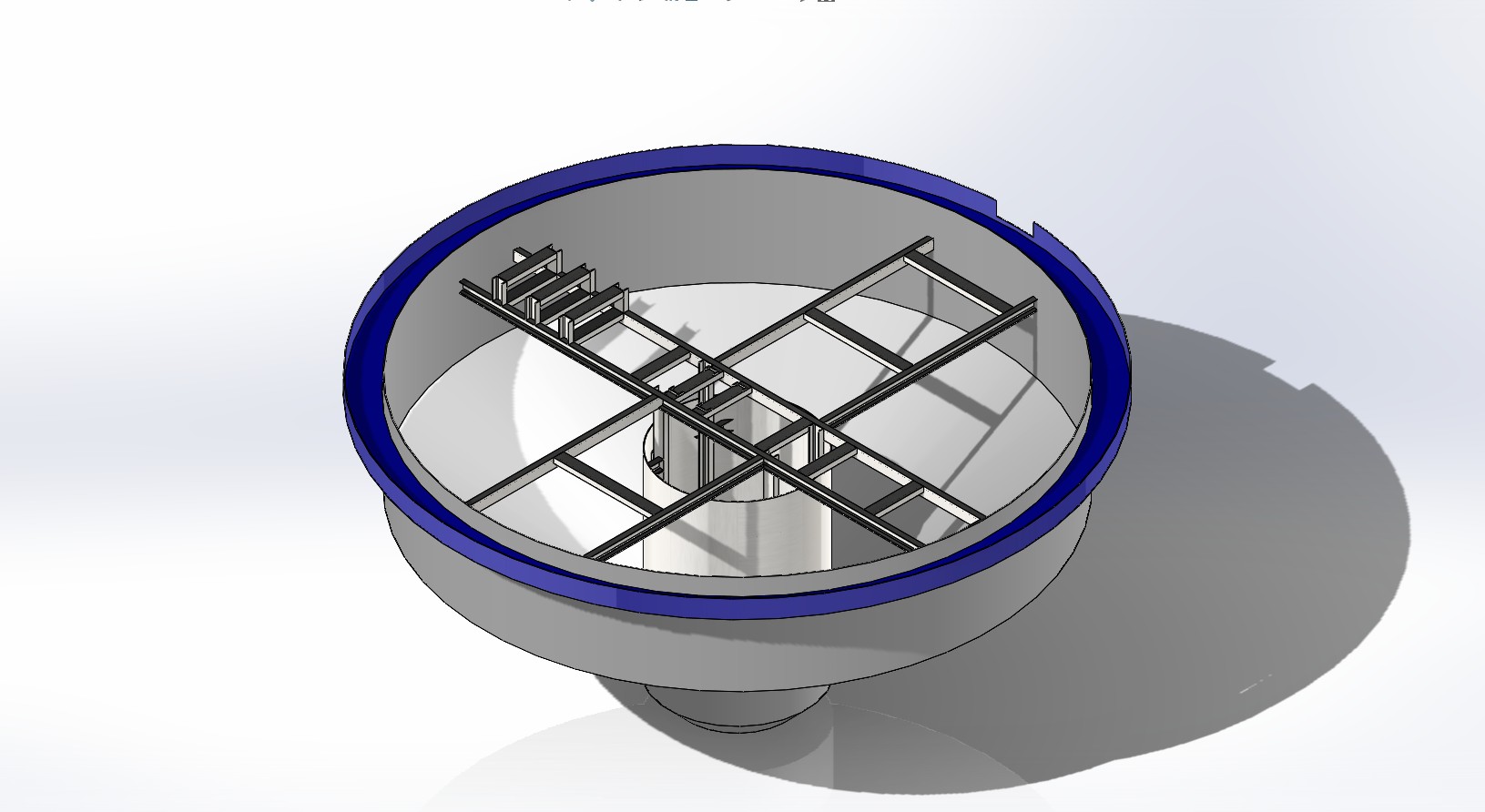
A Practical Guide to Simulating Clarifier Tank Sludge Settling Using OpenFOAM
Simulating sludge settling in a clarifier tank requires a reliable and systematic workflow. This article provides a complete Standard Operating Procedure (SOP) for running a multiphase simulation using the driftFluxFoam solver in OpenFOAM. We will cover the entire process, starting from importing your SolidWorks 3D geometry to solving common mathematical instabilities that occur during the calculation process.
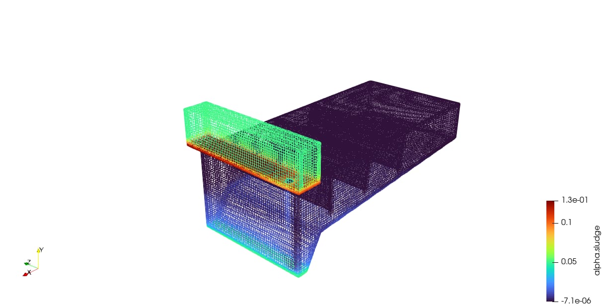
Phase 1: Project Initialization
It is highly recommended not to build a multiphase simulation from scratch. Always clone a validated base case to ensure you inherit the correct file directory structures and fundamental mathematical models.
1. Clone the Base Tutorial
Copy the tank3D multiphase tutorial into your active working directory. This tutorial already provides the necessary BinghamPlastic viscosity framework for sludge modeling.
cp -r $FOAM_TUTORIALS/multiphase/driftFluxFoam/ras/tank3D ./clarifier_tank
cd clarifier_tank
2. Clean the Directory
Remove any pre-calculated mesh or run data from the tutorial so you can start with a clean environment.
foamCleanTutorials
Phase 2: Geometry and Meshing (snappyHexMesh)
1. Import the CAD Model
First, export your 3D tank assembly from SolidWorks into an ASCII .stl format. Place this file inside the constant/triSurface/ directory of your OpenFOAM project.
2. Define the Base Grid (system/blockMeshDict)
Edit the blockMeshDict file to create a bounding box that completely covers your STL geometry. Keep the cell sizes uniform and slightly larger than your targeted fine mesh. Run the following command to generate the background grid:
blockMesh
3. Configure the Mesh Carving (system/snappyHexMeshDict)
Update this dictionary file to reference your specific STL file:
- Set the
geometryblock to match your STL file name. - Define your boundary patches (for example:
inlet,outlet,walls). - Set the
locationInMeshto an X-Y-Z coordinate that is strictly inside the fluid volume of the tank, but outside of any solid baffles.
4. Carve the Geometry
Extract the sharp edges of your model and run the meshing tool. Instruct the software to overwrite the initial block mesh with your complex tank geometry.
surfaceFeatureExtract
snappyHexMesh -overwrite
5. Crucial Quality Check
Run the checkMesh command. You want to see a "Mesh OK" message. If the software identifies "highly skew faces" (for instance, 98 skewed cells located in sharp corners), you must take note of this. You will need to strengthen the numerical solver in the later steps to handle these imperfections.
Phase 3: Boundary and Physics Mapping
Because you are using a custom geometry, the default tutorial boundary names will not match your STL patches. You must align the mathematical conditions with your actual physical design.
1. Clean and Map Boundaries (0/ directory)
Delete any default tutorial boundaries (such as SYMP3 or INLE1) inside the boundary files located in your 0/ folder (U, p_rgh, alpha.sludge, k, epsilon, nut). Replace them with your exact STL patch names (inlet, outlet, walls).
2. Set the Inlet Concentration (0/alpha.sludge)
Define the incoming slurry concentration at the inlet patch. For a 5% sludge mixture, configure it as follows:
inlet
{
    type            fixedValue;
    value           uniform 0.05;
}
3. Set Gravity Direction (constant/g)
Align the OpenFOAM gravity vector with your SolidWorks coordinate system. If the Z-axis is pointing up in your CAD software, use:
value uniform (0 0 -9.81);
4. Define Fluid Properties (constant/transportProperties)
Set the density (rho) and kinematic viscosity (nu) for both fluid phases in the system.
- Water:
rho 1000;,nu 1e-06; - Sludge:
rho 1200;,nu 1.5e-06;(Note: Adjust therhovalue based on your actual slurry density data).
Phase 4: Time Control and Execution
1. Set the Simulation Master Clock (system/controlDict)
In this step, we configure the physical simulation time and activate the automatic safety features to prevent software crashes during high turbulence.
endTime 3600;(Represents 1 hour of physical settling time).writeInterval 300;(Saves 3D visual data every 5 physical minutes).adjustTimeStep yes;(Allows OpenFOAM to automatically shrink time steps to maintain calculation stability).maxCo 0.5;andmaxAlphaCo 0.5;(Applies strict speed limits for maximum stability).
2. Run the Solver
Execute the mathematical solver in the background. It is best practice to log the terminal output to a text file so your terminal interface remains usable for other tasks.
driftFluxFoam > log.driftFluxFoam &

Phase 5: Troubleshooting Guide (Crash Recovery)
When simulating massive industrial volumes, multiphase solvers often experience numerical crashes. This usually happens when complex flow eddies hit slightly distorted mesh cells around corners or baffles.
Diagnostic Step 1: Identify the crash type by running tail -f log.driftFluxFoam in your terminal and analyzing the last few lines before the stack trace error.
Issue A: Continuity Errors Explode (Mass Loss)
Symptom: time step continuity errors : sum local = 2.38e+26. The simulation loses track of the fluid mass. This is usually triggered by highly skewed mesh faces.
The Fix (Add Correctors):
- Open the
system/fvSolutionfile. - Locate the
PIMPLEblock. - Increase the non-orthogonal correctors to force the solver to double-check its calculations around bad mesh angles:
nNonOrthogonalCorrectors 2; - Open
system/controlDict, change the setting tostartFrom latestTime;, and restart the solver.
Issue B: Courant Number Spikes
Symptom: Courant Number max: 4.19e+07. The calculated fluid velocity mathematically accelerated to infinity.
The Fix (Tighten the Safety Net):
- Open the
system/controlDictfile. - Ensure the
adjustTimeStep yes;parameter is active. - Lower the maximum allowed Courant numbers to force the software to use smaller time steps (
deltaT):maxCo 0.3;andmaxAlphaCo 0.3; - Restart the solver.
Issue C: Volume Fraction Overshoot (Alpha > 1.0)
Symptom: Max(alpha.sludge) = 55.5. The solver mathematically crammed 5,500% sludge volume into a single mesh cell. This causes the viscosity equations to divide by zero and immediately crash.
The Fix (Enable Upwind Schemes):
- Open the
system/fvSchemesfile. - Locate the
divSchemesblock. - Replace mathematically sharp (but highly unstable) schemes like
Gauss linearUpwindorGauss vanLeerwith maximum-stabilityupwindschemes for your velocity, sludge, and turbulence parameters:div(rhoPhi,U) Gauss upwind; "div\(phi,alpha.*\)" Gauss upwind; "div\(phirb,alpha.*\)" Gauss upwind; div(rhoPhi,k) Gauss upwind; div(rhoPhi,epsilon) Gauss upwind; - Restart the solver. The
upwindscheme acts as a numerical shock absorber and strictly bounds the volume fraction results between 0 and 1